![]()
Now in colour!
• Chris Liscio
![]()
• Chris Liscio
Last night, after buying some potentiometers and going back to my original design containing transistor amps on the colour inputs, I have claimed yet another small victory in the VGA->LCD project.</p><p>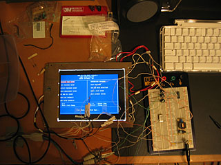 </p><p>So now I have two options:
1. Continue to lay out the PCB given my new, successful design.
2. Perfect the circuit to include a PIC 16F84 that handles the centering of the displayed image, and then lay out the PCB.</p><p>Decisions, decisions. I think I will have to choose option 1 due to my lack of time right now. It is a little annoying to have the image chopped off on the left side of the TFT due to one control line on the interface that I'm unable to drive properly. Then again, it only takes about 20 minutes to throw together a little program to run on the PIC that'll drive the ENAB line of the TFT. We'll see what I can pull off for the time being.</p><p></p>